PCB trace width is one of the most important layout decisions in a circuit board design. A trace that is too narrow may overheat, create excessive voltage drop, or reduce long-term reliability. A trace that is too wide may waste valuable board space and make routing more difficult.
For engineers designing power electronics, LED drivers, battery-powered devices, industrial controllers, and consumer products, understanding trace width and current capacity helps prevent avoidable manufacturing and performance problems.
What Determines PCB Trace Current Capacity?
The current capacity of a PCB trace depends on several factors working together. The most important ones are copper thickness, trace width, allowed temperature rise, trace length, ambient temperature, and whether the trace is on an internal or external layer.
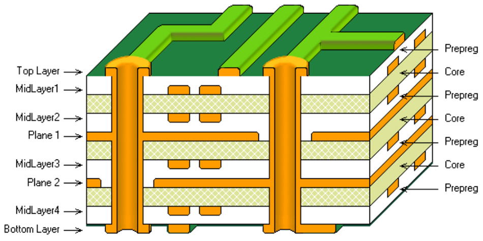
External traces can usually carry more current than internal traces of the same width because they dissipate heat more easily into the surrounding air. Internal traces are surrounded by dielectric material, so heat removal is less efficient.
Copper Thickness Matters
Standard PCB copper thickness is often 1 oz, which is approximately 35 micrometers. For higher current applications, designers may choose 2 oz or heavier copper. Increasing copper thickness allows a trace to carry more current without requiring the same increase in width.
However, heavier copper can affect minimum spacing, etching precision, cost, and lead time. It is best to confirm these requirements with your PCB manufacturer before finalizing the design.
Temperature Rise and Reliability
Trace width calculations are usually based on an acceptable temperature rise, such as 10°C, 20°C, or 30°C above ambient. A higher allowed temperature rise means the trace can be narrower, but it may also increase thermal stress on the board and nearby components.
For products that must operate continuously, in enclosed housings, or in warm environments, it is safer to use conservative trace widths. Reliability is not only about whether the board works during testing. It is also about whether it keeps working after months or years in real use.
Do Not Ignore Voltage Drop
Even if a trace can safely carry the required current, it may still create too much voltage drop if it is long or narrow. This is especially important for low-voltage circuits, high-current LED boards, motor drivers, battery paths, and sensitive analog circuits.
When voltage drop matters, designers should consider wider traces, shorter routing paths, copper pours, parallel traces, or dedicated power planes.
Practical Design Tips
- Use a PCB trace width calculator as an initial reference, then add a safety margin.
- Keep high-current traces as short and direct as possible.
- Use copper pours or planes for power distribution when board space allows.
- Avoid routing high-current traces through narrow neck-down sections.
- Use thermal vias when transferring current or heat between layers.
- Confirm heavy copper, spacing, and manufacturing limits before production.
When to Discuss Trace Width with Your PCB Manufacturer
If your board uses high current, heavy copper, narrow spacing, high temperature operation, or strict reliability requirements, it is worth discussing the stack-up and copper design before production. A good manufacturer can review whether your trace width, copper thickness, and spacing are realistic for fabrication.
At EazyPCB, we support prototype and production PCB manufacturing for applications ranging from consumer electronics to industrial and power-related products. If you are unsure whether your layout is suitable for manufacturing, our team can help review the key production requirements before your order moves forward.