
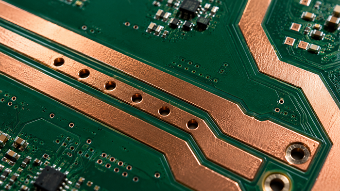
PCB copper thickness is one of the key factors that affects current capacity, heat dissipation, voltage drop, mechanical strength, and manufacturing cost. A design that works well with 1 oz copper may need wider traces, extra copper pours, or thicker copper when the current becomes higher.
For many standard PCB fabrication projects, 1 oz copper is enough. For power electronics, motor control, LED lighting, battery systems, industrial equipment, and automotive modules, 2 oz or heavy copper may be required.
What Does 1 oz Copper Mean?
PCB copper thickness is often described by copper weight. 1 oz copper means one ounce of copper spread over one square foot of area. In finished PCB terms, this is approximately 35 micrometers of copper thickness before considering process variations and plating.
1 oz copper is widely used because it offers a good balance between cost, manufacturability, and electrical performance. It is suitable for many consumer electronics, control boards, communication products, and general embedded systems.
What Is 2 oz Copper?
2 oz copper is roughly twice the thickness of 1 oz copper. It can carry more current with the same trace width, or allow a narrower trace for the same current compared with 1 oz copper.
However, thicker copper also affects etching, spacing, solder mask, and fine-pitch manufacturability. If a design uses 2 oz copper, the minimum trace width and spacing may need to be larger than a standard 1 oz board.
What Is Heavy Copper PCB?
Heavy copper PCB usually refers to boards using copper thickness greater than standard 1 oz or 2 oz copper. Depending on the project, heavy copper may include 3 oz, 4 oz, 5 oz, or even higher copper weights.
Heavy copper boards are common in high-current and high-reliability applications. They can improve current handling and thermal performance, but they also require careful design rules, suitable materials, and manufacturer confirmation.
How Copper Thickness Affects Current Capacity
Current capacity depends on copper thickness, trace width, allowed temperature rise, board environment, copper location, and cooling conditions. A thicker copper layer can reduce resistance and help carry more current, but it does not remove the need for proper trace width calculation.
For more detail, see our PCB trace width and current capacity guide. Trace width, copper thickness, copper area, and thermal design should be considered together.
Copper Thickness and Heat Dissipation
Thicker copper can help spread heat across the board. This is useful for power components, LED drivers, motor drivers, voltage regulators, and high-current connectors.
Still, copper thickness is only one part of thermal design. Designers should also consider copper pours, thermal vias, component placement, substrate material, board thickness, airflow, and enclosure conditions.
Manufacturing Trade-Offs
Increasing copper thickness can improve electrical and thermal performance, but it may also increase cost and reduce fine-detail capability. Heavy copper is harder to etch precisely, so very fine traces and small spacing may not be suitable.
Before choosing heavy copper, it is useful to review the overall PCB DFM checklist. Confirm minimum trace width, spacing, solder mask clearance, finished copper thickness, and panel requirements before production.
Material and Stack-Up Considerations
Copper thickness should match the PCB material and stack-up. Standard FR-4 may be enough for many power boards, but high-temperature, high-power, aluminum substrate, or special material designs may need additional review.
Our PCB material selection guide explains how FR-4, high-TG FR-4, aluminum, Rogers, and PTFE materials are used in different applications.
When Should You Use 1 oz, 2 oz, or Heavy Copper?
- Use 1 oz copper for many standard signal, control, and low-power boards.
- Use 2 oz copper when current is higher or trace width is limited.
- Use heavy copper for power electronics, motor drives, battery systems, and high-current designs.
- Use wider copper pours and thermal vias when heat spreading is important.
- Confirm manufacturability when combining thick copper with fine-pitch components.
Standards and Design Communication
Standards help designers and manufacturers communicate requirements clearly. The IPC standards family is widely used in PCB design and manufacturing, and IPC-2221 is often referenced for general printed board design guidance.
For production projects, copper thickness should be specified clearly in fabrication notes. If the finished copper thickness is critical, mention whether the requirement applies to outer layers, inner layers, or both.
Choose Copper Thickness Early
Copper thickness should not be decided at the last minute. It affects trace width, spacing, stack-up, thermal design, cost, and lead time. Choosing it early helps avoid redesign before production.
EazyPCB supports prototype and volume production PCB projects with standard and advanced manufacturing capabilities. If you need help reviewing copper thickness, high-current traces, or heavy copper feasibility, you can contact our engineering team before placing an order.
