
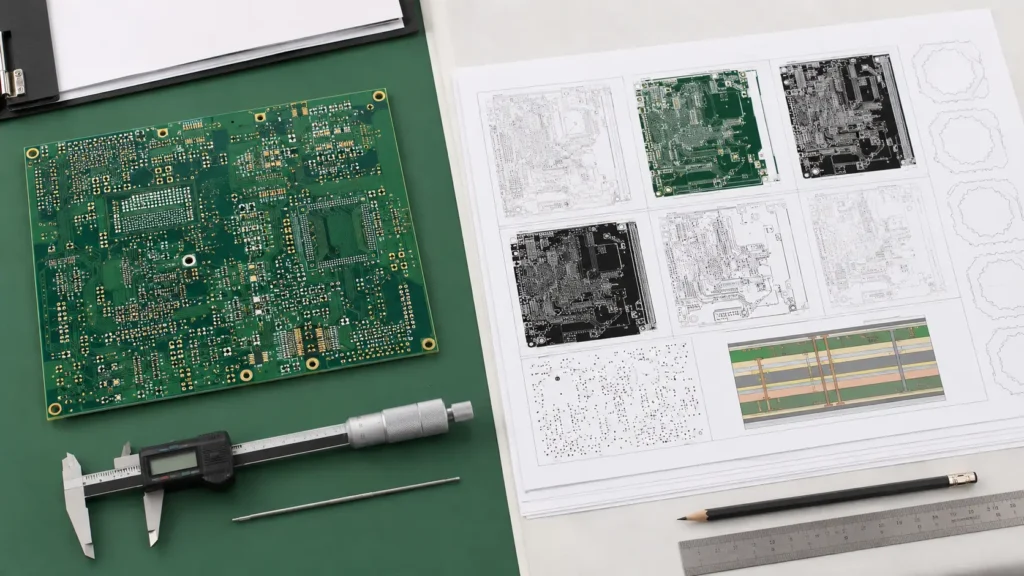
A quotation can be accurate enough to discuss price and still be incomplete for production. That difference becomes visible when CAM review starts. The copper data shows one outline, the drawing shows another. The order says 1.6 mm, while the stack-up adds up differently. A slot appears in the mechanical layer but is missing from the drill data. None of these questions is unusual, but each one needs an approved answer before the board is released.
A production-ready PCB manufacturing release package is more than a ZIP file of Gerbers. It is a controlled statement of design intent: which revision is current, what the finished board must be, which data drives each feature, and who can approve a change. Understanding the complete PCB manufacturing process makes it easier to see why a small document conflict can affect tooling, material planning, drilling, plating, inspection, or delivery.
Release principle: A file package is ready for production only when a fabricator can answer every manufacturing question from the approved data without guessing which note, email, or attachment takes priority.
1. Quote-Ready and Production-Ready Are Different States
For an early quotation, a manufacturer may be able to estimate from preliminary Gerber data, layer count, size, material, copper, finish, quantity, and a few special requirements. Production needs a narrower definition. Dimensions must agree, controlled features need tolerances, the stack-up must be accepted, and obsolete files must be removed.
| Information area | Often enough for quotation | Needed for production release |
|---|---|---|
| Board definition | Approximate size, layer count, quantity | Closed profile, cut-outs, dimensions, tolerances, array status |
| Construction | Material family, nominal thickness, copper | Approved stack-up, finished thickness, finished copper, special build notes |
| Holes and routing | General drill complexity | NC drill and route data, plated status, depth-controlled features, tolerances |
| Special requirements | Impedance or special finish noted | Targets, references, coupon rules, edge plating, marking, acceptance criteria |
| Revision status | Preliminary file name | One approved revision, manifest, release date, named approver |
The earlier Gerber file checklist is useful for checking exported layers. The release package goes one step further by controlling the relationship between every file and every written requirement.
2. Establish One Master Revision
Revision control sounds administrative until two technically valid files describe different boards. A reliable handoff starts with one project identifier and one release revision used across the archive name, fabrication drawing, assembly drawing, BOM, pick-and-place file, test specification, and approval record.
Do not leave an older drill file or drawing in the production archive “for reference.” Put superseded files outside the released package. A simple manifest should list the included files, revision, date, units, and purpose. If a late change is approved, issue a new complete package rather than sending one replacement layer through an email thread.
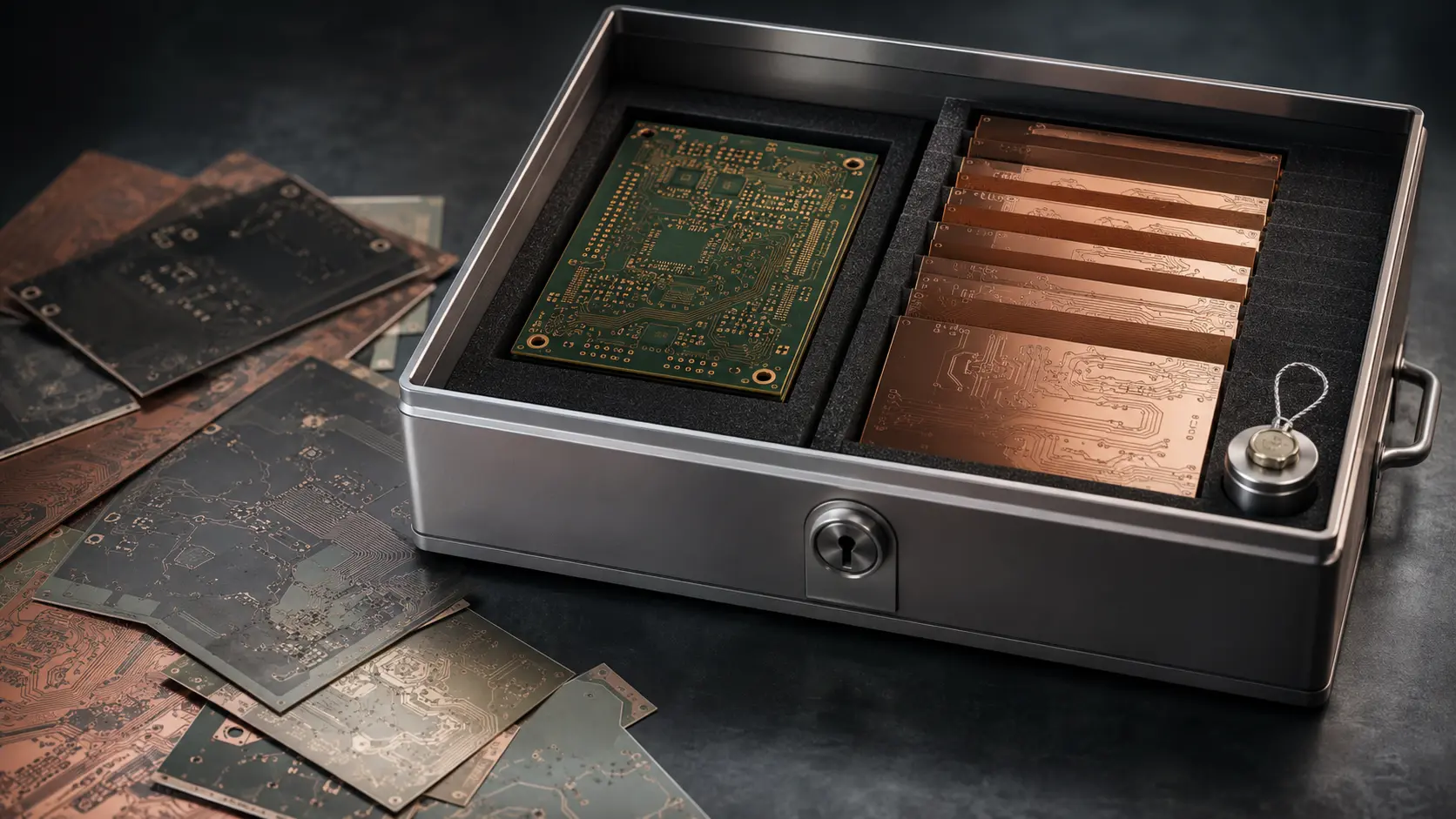
Common release mistake: Sending a new copper layer while assuming every other file remains compatible. A local edit can also affect drill alignment, solder mask, legend, netlist, impedance, panelization, or assembly data. Re-export and review the complete set.
3. Make the Fabrication Data Machine-Readable
A traditional fabrication package normally includes Gerber layer data plus NC drill and route files. Intelligent formats such as IPC-2581 can carry a broader set of product and manufacturing information in a structured exchange. The best format is the one agreed with the fabricator and exported correctly from the design system.
Ucamco’s official Gerber resources explain that Gerber layers represent items such as copper, solder mask, legend, drill, and route data, while attributes can communicate layer and object information. The IPC-DPMX / IPC-2581 Consortium describes IPC-2581 as an open standard for exchanging PCB design, fabrication, assembly, and test information.
Whatever format is selected, check four basics before release: all layers share the same coordinate system, data is not accidentally mirrored, scale and units are unambiguous, and the machine-readable profile is a clean closed outline. A PDF outline drawing helps a person understand the board, but it should not be the only definition used to create routing data.
4. Use the Fabrication Drawing to State Finished Requirements
Image data defines geometry. The fabrication drawing should define the finished product where geometry alone is not enough. Typical items include finished board thickness, material or performance requirement, finished copper by layer, surface finish, solder mask and legend, dimensional tolerances, controlled-depth features, edge treatment, panel requirements, and any special marking.
For multilayer boards, the drawing and data package should agree with the approved stack-up. The practical reason is simple: dielectric construction affects finished thickness, drill aspect ratio, copper balance, and controlled impedance. The multilayer PCB manufacturing guide explains these relationships in more detail.
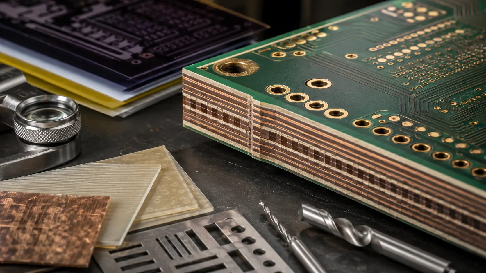
Decision point: Do not use a tight tolerance simply because the CAD tool can display many decimal places. Identify which dimensions affect enclosure fit, connectors, press-fit parts, edge contacts, heat spreaders, or mating hardware, then discuss those requirements with the PCB fabrication team.
5. Preserve Electrical Test Intent
Electrical testing checks the manufactured board against expected connectivity. A netlist exported from the design source, when available and supported by the agreed workflow, provides intent that is independent of the image-derived production data. This can help expose a data export or editing error that would otherwise be repeated in both manufacturing data and a test program derived from it.
IPC lists IPC-D-356 among its design standards for bare-board electrical test information in digital form. The exact test method and acceptance requirements still need to be agreed for the project. Continuity and isolation testing cannot prove every material, dimensional, impedance, or reliability requirement, so it belongs inside a broader PCB manufacturing quality plan.
6. Resolve Conflicts Before the Release Gate
CAM review is most efficient when the package tells the reviewer how to resolve information, not when the reviewer has to infer design intent. The following conflicts deserve a written answer before tooling is finalized.
| Conflict | What is at risk | Release action |
|---|---|---|
| Drawing and order specify different thickness or finish | Material planning, connector fit, solderability | Correct both sources and issue one approved value |
| Profile differs between Gerber and mechanical drawing | Routing, enclosure fit, panel tooling | Release a closed master profile and matching dimensioned drawing |
| Drill table and NC drill data disagree | Finished hole size, plating status, component fit | Re-export or correct the source; identify plated and non-plated holes |
| Stack-up revision differs from copper data | Layer order, impedance, lamination construction | Approve one layer sequence and regenerate affected documentation |
| Email instruction changes a released requirement | Traceability and repeat-order consistency | Move the decision into a revised controlled package |
Stop-release rule: If two active documents define the same feature differently, do not solve the conflict by adding another informal note. Correct the source files, update the revision, and release the package again.
7. Add Assembly Data When the Order Includes PCBA
Bare-board release data is not enough for assembly. A PCBA package may also require an approved BOM, centroid or pick-and-place data, assembly drawings, polarity references, do-not-fit information, stencil instructions, programming files, and a test specification. Reference designators and board origin must agree across these files.
The BOM and pick-and-place checklist covers the assembly handoff in detail. If fabrication and SMT assembly are released together, manage both as one product revision so a board change does not leave the assembly package behind.
8. Use a Short, Repeatable Release Workflow
- Export from the approved design source. Avoid hand-editing manufacturing files unless the change is controlled and reviewed.
- Open the exported data independently. Check layer identity, alignment, polarity, profile, drills, text, mask openings, and obvious missing content.
- Run the design review. Use a practical PCB DFM checklist and resolve exceptions.
- Compare every document. Confirm drawing, stack-up, order fields, netlist, and assembly data describe the same revision.
- Create the manifest. State project, revision, date, units, included files, special requirements, and approver.
- Freeze and archive the release. Keep the exact approved package for repeat orders and future failure analysis.

Practical handoff note: Put a one-page manifest at the top of the package. It can be simple, but it should answer these questions:
- What product and revision is this?
- Is the package for quotation, prototype, or production?
- Which files are authoritative?
- Which features need special review?
- Who can approve a technical deviation?
Final Thoughts
A clean PCB manufacturing release does not eliminate engineering questions. It makes those questions visible while changes are still inexpensive and traceable. The strongest package is not the one with the most files; it is the one in which every active file describes the same board and every critical requirement has an owner.
EazyPCB supports PCB fabrication, DFM review, prototyping, SMT assembly, inspection, and production coordination. To review a new release package, contact EazyPCB with the current revision, fabrication data, drawing, stack-up, quantity, and any critical mechanical or electrical requirements.
