Rogers PCB
Manufacturing multilayer PCB up to 56 layer, IPC III Standard, Multilayer Rigid PCB, Multilayer Flex PCB, Rigid-flex Board, hybrid PCB…
Personal Information
Introduction
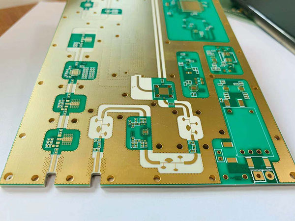
Rogers PCBs (high-frequency circuit boards) are specialized printed circuit boards designed for high-frequency and high-speed signal transmission. Widely used in 5G communications, radar systems, satellite equipment, and aerospace applications, Rogers PCBs differ from traditional FR-4 substrates by utilizing high-performance ceramic-filled polytetrafluoroethylene (PTFE) materials. These boards offer exceptional dielectric constant stability, low loss tangent, and superior thermal management. This article explores their core technical features and application advantages.
1. Manufacturing Process Overview
Rogers PCB fabrication requires strict adherence to specialized high-frequency material processes:
Material Pre-Treatment: Rogers substrates must be stored in temperature- and humidity-controlled environments to prevent moisture absorption, which degrades dielectric properties.
Drilling and Etching: Laser drilling ensures precision for micro-vias, while chemical etching controls copper thickness to meet impedance requirements.
Lamination: Multilayer bonding demands precise temperature (typically below 300°C) and pressure control to avoid PTFE deformation.
2. Material and Structure
Key material characteristics of Rogers PCBs:
Substrate Types: RO3000® series (ceramic-filled PTFE) and RO4000® series (hydrocarbon + ceramic).
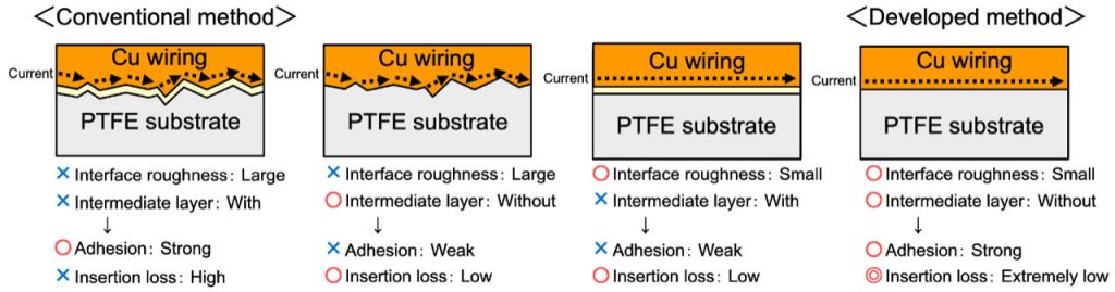
Copper Foil: Low-profile reverse-treated foil (RTF) or rolled copper minimizes skin effect losses during signal transmission.
Multilayer Design: High-frequency signal layers are alternated with ground layers, and hybrid dielectric materials (e.g., RO4450B™) balance cost and performance.
3. Design Considerations
Critical factors for Rogers PCB design:
Impedance Control: Calculate trace width and spacing based on Dk values (e.g., RO4350B’s Dk=3.48).
CTE Matching: Align the coefficient of thermal expansion (CTE) between copper and substrate to prevent delamination under high temperatures.
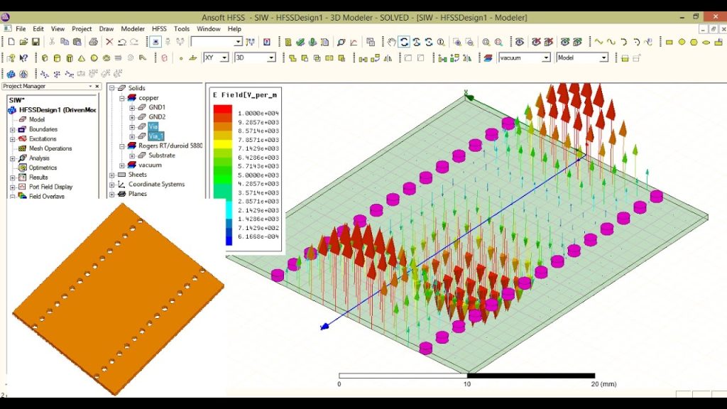
Loss Optimization: Use simulation tools (e.g., ANSYS HFSS) to refine trace length and termination designs.
4. Modeling and Analysis
High-frequency signal integrity relies on accurate modeling:
EM Simulation: 3D full-wave simulations (e.g., HFSS) validate insertion loss and return loss across signal paths.
Thermal Analysis: Evaluate heat distribution from power components to ensure temperatures remain below the substrate’s glass transition temperature (Tg), e.g., RO4835’s Tg >280°C.
5. Signal Integrity Management
Strategies for high-frequency signal integrity in Rogers PCBs:
Loss Mitigation: Select materials with low dissipation factors (Df), such as RO3003 (Df=0.0013@10GHz).
Crosstalk Reduction: Implement via fencing and differential pair routing to minimize interference.
Termination Matching: Use embedded resistors or AC coupling capacitors to address signal reflection.
6. Cost Optimization
Balancing performance and affordability:
Hybrid Stackups: Use Rogers materials only for critical high-frequency layers, combined with FR-4 for cost savings.
Bulk Purchasing: Negotiate long-term agreements with Rogers Corporation for volume discounts.
Yield Improvement: Apply DFM (Design for Manufacturing) guidelines to reduce scrap rates.
Conclusion
Rogers PCBs have become the gold standard for millimeter-wave communications and high-speed digital systems due to their unmatched high-frequency performance and reliability. Designers must balance material selection, simulation validation, and cost efficiency while adhering to specialized manufacturing protocols. As 6G technology and automotive radar systems evolve, Rogers PCBs will continue to drive innovation in cutting-edge electronics.
Contact
805, Block A, Guangming Centre, No. 2, Chuangming Road, Yongning Street, Zengcheng District, Guangzhou, China
- op@eazypcb.com
- Eazypcb
- +86 13342868540